
Almost all TNCs in my collection do already have some sort of open squelch data carrier detection (DCD). Mostly XR2211 PLL IC based DCDs and some are having a TAPR or Paccomm DCD state-machine kit built-in.
Using a TNC without open squelch DCD isn’t that satisfying nowadays on CB but I still had some TNCs laying around I’d like to test for real. Compared to the 90s the noise floor is raised and QRM fluctuates a lot more. Chances are high a TNC would never go into TX at certain levels or at least can’t function properly with the squelch set to a fixed level.
Therefore I was looking to some options. The TAPR DCD state-machine kits were great, but aren’t available anymore and (very) hard to find… XR2211 based open squelch DCD was still an option, but has some caveats… Also found 2 projects on the internet from guys using a microcontroller. One published a schematic, but no firmware at all. The other one published a schematic and .hex binary.
Although I didn’t have intentions to reinvent ‘the wheel’ it felt like a nice one for some sort of mini-project. Some techniques are very straightforward and easy/ideal to accomplish with the help of a small microcontroller. After reading a bit of info, mainly in very old documents, I had thoughts: “Why NOT making one myself”? It should be easy to make one with a minimal amount of components which also outperforms ‘most oldtimers’, especially the XR2211 based ones…
And there I went programming a bit.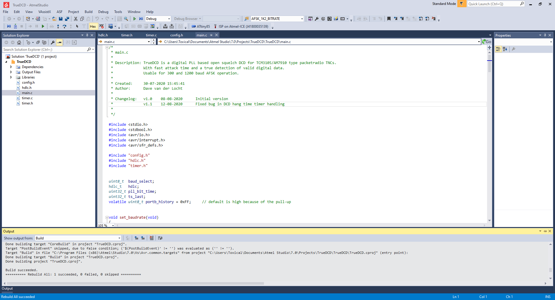
There are a couple of methods to accomplish data carrier detection on the receive data output of a TCM3105 or AM7910 modem IC which are widely used in many TNC2 type/clone TNCs like an AEA PK-88, Paccomm Tiny-2 and Tiny-2 MK-2, TNC2C-NL/DE etc. etc.
I’ve choosen to use a digital PLL method to recover the appropriate bits from the datastream coming out a TNCs modem IC. After recovery it does some (basic) checks on the data link layer to distinguish/recognize real 300 or 1200 baud packet radio data from all other rubbish coming out the modem IC. This open squelch DCD should therefore only react on real data with the least amount of false-positives. The PLL method derived from another build (Baycom <-> KISS USB interface) where I’ve used the exact same technique with good results.
Basically the microcontroller just ‘waits’ until it succesfully decodes a couple of HDLC flags (0x7E). That’s the right trigger for the TNCs DCD signal. After a complete HDLC frame the DCD signal should be released with a small ‘DCD hang time’ taken in account, its optimal time should be about 8 times a bit period according to some old documentation I found.
Some of my mini-project’s requirements were:
– True data carrier detection with least amount of false-positives
– Fast attack time
– Suitable for 300 and 1200 bps
– Using a minimal amount of components
– Compatible with TNCs using a TCM3105 or AM7910 modem IC
A small video of the very first tests with a TrueDCD board placed in a Paccomm Tiny-2 MK-2 connected to a simple Zodiac M-8000 CB radio.
Board is made to fit the DCD option header (J10) in Paccomm’s Tiny-2 MK-2.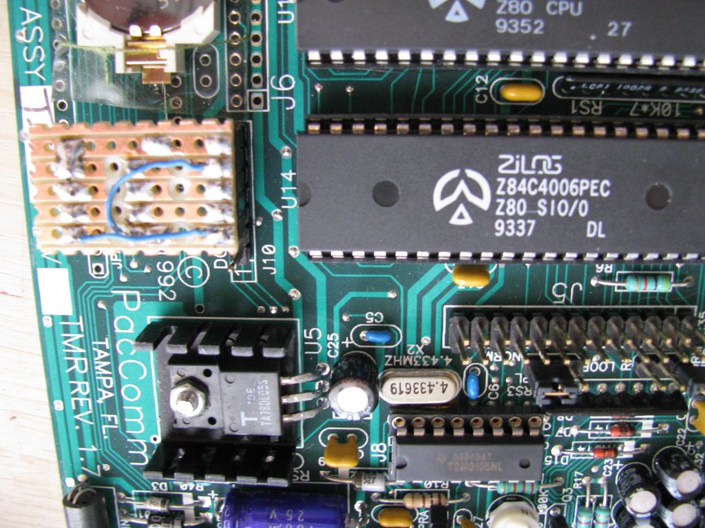
Also made a board for testing/fitting in an AEA PK-88 TNC with AM7910 modem IC.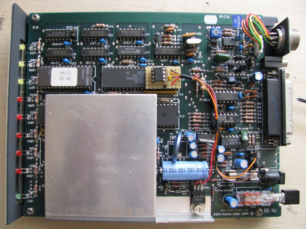
If you’d like to build and try one yourself… Here’s the schematic with some info and firmware binary and an installation instruction.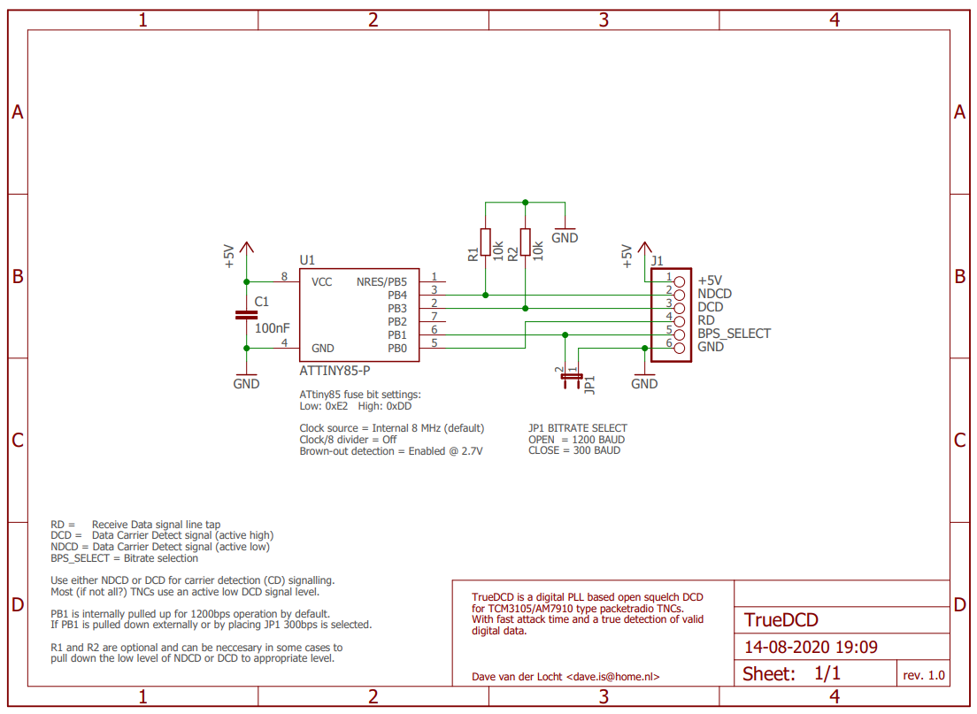


Installation instructions applicable to TAPR TNC2 klones/variants:
1- Connect +5V to the TNC’s voltage regulator 5V output (7805 pin 3)
2- Connect GND to TNC’s voltage regulator GND (7805 pin 2)
3- Connect RD to the TNC’s modem IC receive data output (TCM3105 pin 8 or AM7910 pin 26)
4- Connect NDCD to the Z80 8530 SIO IC pin 19 and interrupt the existing CD connection between the Z80 SIO and TCM3105/AM7910 modem IC.
Basically you need to tap the receive data (RD) from the signalling line between the modem IC and Z80 SIO IC. The next thing is to let the TrueDCD do the carrier detect (CD) signalling instead of the modem IC by interrupting the existing connection and connect TrueDCD’s NDCD output to the Z80 SIO.
In a lot of TNCs there’s already a jumper in the modem’s receive data (RD) and carrier detect (CD) signalling lines. This makes installation pretty easy by using these jumper blocks. In that case there’s no need to solder directly to ICs and/or cutting tracks on the PCB. See the AEA PK-88 image above for example.
In case of any problems:
1- Check if the ATtiny85 has about 5V between pins 4 (GND) and 8 (VCC).
2- Check if you’ve connected the receive data (RD) tap correctly
RD tap = ATtiny85 pin 5 to TCM3105 pin 8 or AM7910 pin 26.
3- Check if you’ve connected the carrier detect (CD) line correctly
CD line = ATtiny85 pin 3 to Z80 8530 SIO pin 19.
4- Check if the existing carrier detect (CD) line between the TCM3105 or AM7910 and the Z80 8530 SIO is interrupted.
5- Check if the ATtiny85 is programmed correctly including the (important!) fusebits.
If all 5 checks are done and seem to be ok, it can be necessary to use a 10k pull-down resistor on TrueDCD’s NDCD output (R1).
If you’re still having issues please check all again, especially check for accidentally wrong connected pins/places.
Thanks for sharing your DCD circuit and code Dave. I built and fitted it to my Maxpak TNC2 clone. It didn’t work first time, but I’d incorrectly set the fuse bits. Once I’d corrected my mistake it worked perfectly.
https://www.youtube.com/watch?v=3jNeae-6aRc
Chris – M0VPN
Hello,
I have built your True Open Squelch DCD and on my 1997 vintage rev 1.92 PacComm Tiny-2 Mk2 it does not work very well.
It will work on strong signals, but not on weaker signals. My Tiny-2 does work on these weak signals with open squelch and also with closed squelch on the radio (without the open squelch mod board in place).
I have added a 10k resistor, R1 but still it will not decode weaker signals.
I do remove the jumper on the JPD pins when the board is fitted and put it in place for standard operation.
Any ideas how to improve things?
Thanks in advance.
Hi Nigel,
The True Open Squelch DCD takes the data signal for carrier detection from the (digital) data output of the TCM3105 to the Z80 SIO. This shouldn’t alter decoding rate / performance with weaker signals. It’s the TCM3105 which (still) does the FSK demodulation. The True Open Squelch DCD only ‘looks’ at the same signal as the Z80 SIO does for decoding.
Decoding performance however might degrade if there’s something wrong with the voltage regulation or RX bias (TCM3105 pin 7). You might check/compare the ripple voltage with DCD board installed/uninstalled at the +5V pin of the TCM3105. It might get to much when there’s more current drawn which can degrades decoding performance. And check if the RX bias pin has a voltage about 2,7V.
Most problems I’ve seen with bad decoding is due to bad voltage regulators or bad capacitors at the voltage in/output around the regulator.
Hey Dave!
Thanks for sharing your DCD. Will give it a try soon, because my old Landolt TNC2C came without any.
Is there any chance you release the source code? Just want to have a look inside the “magic”, to understand how things work.
Thanks in advance
Marcus